


PRODUCT CATEGORY


Introduction:
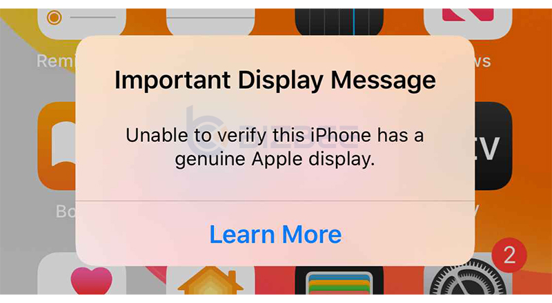
If you replace the screen of iPhone 11 or above, whether it is a genuine screen or a third-party repair display, you will see the “Important Display Message” on the iPhone (As shown in the figure below). It mentions unable to verify this iPhone has a genuine Apple display. Now here’s a solution to fix it, read more, and you will find what you want.
PS: Suitable for iPhone 11, iPhone 11 Pro, iPhone 11 Pro Max
Video Overview
Operation Method
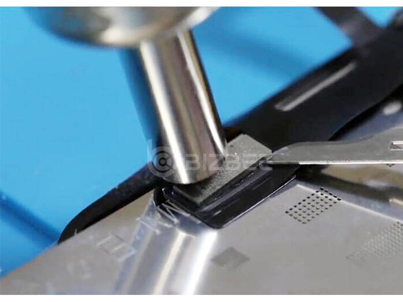
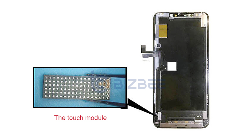
Step 1: Remove touch module
Tear down the touch module from the original display, use hot air gun to blow and steel tool to pry carefully.
Step 2: Clean out the touch module
Clean out the black adhesive from the module with solder flux and solder wick and heat up with hot air gun.
Step 3: Connect the touch module to the touch module connector (please refer to the video for detail operation)
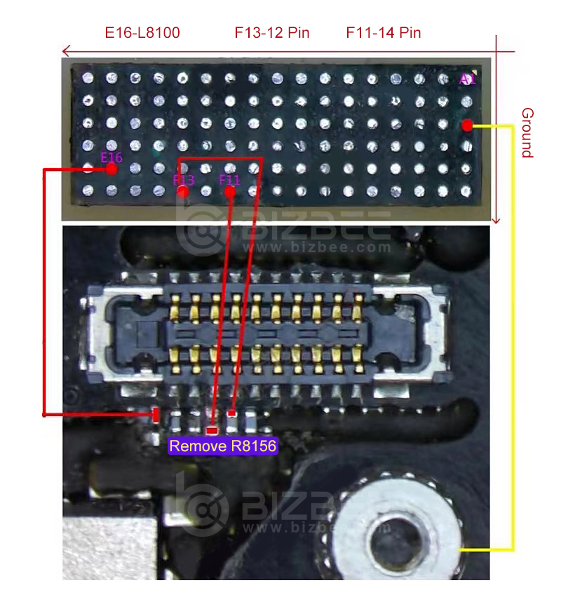
For iPhone 11:
1) Find the touch module connector on the mobile phone main board as the picture shows below. Remove the resistor R8156 which is next to the touch module connector.
2) Use conductivity copper conductor to connect F11-14 pin (12C3 bus data signal), to the data signal point of the resistor R8156.
3) Find the position of the inductor L8100 (1.8V power supply) next to the touch module connector as the picture shows, and connect E16 to L8100.
4) Find the position of the capacitive clock signal and connect it to F13-12 Pin.
5) Find the ground-to-ground pin on the touch module, and connect it to the ground-to-ground position of the main board.
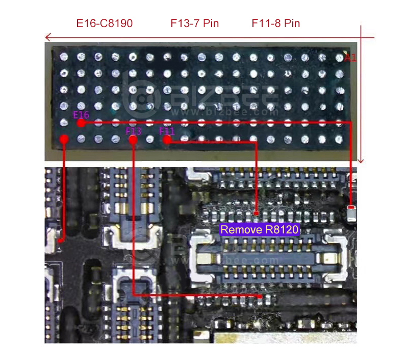
For iPhone 11 Pro and iPhone 11 Pro Max:
1) Find the touch module connector on the mobile phone main board as the picture shows below. Remove the resistor R8120 which is next to the touch module connector.
2) Use conductivity copper conductor to connect F11-8 pin (12C3 bus data signal), to the data signal point of the resistor R8120.
3) Find the position of the capacitor C8190 (1.8V power supply) which is next to the touch module connector as the picture shows, and connect it to E160.
4) Find the position of the capacitor C8121 (clock signal) which is next to the touch module connector, and connect it to F13-7 Pin.
Find the ground-to-ground pin on the touch module, and connect it to the ground-to-ground position of the main board.
Step 4: Find a place to fix the touch module
Find a place to fix the touch module. It is recommended to fix it between the battery and the main board as the video shows.
For more details and latest price, please contact us:
Email: service@bizbee.com
Sign up and Get Your Dedicated Account Manager


 iPhone Cases
 Samsung Phone Cases
 Xiaomi Phone Cases
 OPPO Phone Cases
 VIVO Phone Cases
 Transsion Infinity Phone Cases
 iPad Cases & Covers
 Galaxy Tab Cases & Covers
 Matepad Cases & Covers
 Mipad Cases & Covers
 Lenovo Tab Cases & Covers
 Honor Tablets Cases & Covers
 AirPods Cases
 Laptop Bags & Cases
 iPhone Screen Protectors
 Samsung Screen Protectors
 Xiaomi Screen Protectors
 OPPO Screen Protectors
 VIVO Screen Protectors
 Other Screen Protectors
 iPad Screen Protectors
 Galaxy Tab Screen Protectors
 Matepad Screen Protectors
 Mipad Screen Protectors
 Lenovo Tab Screen Protectors
 Other Tabets Screen Protectors
 Macbook Screen Protectors
 Other Laptops Screen Protectors
 Lens Protectors
 Apple Watch Bands
 Samsung Galaxy Watch Bands
 Mi Watch Bands
 Garmin Bands
 Amazfit Bands
 Fitbit Bands
 Huawei Watch Bands
 Desktop Phone Stands
 Car Phone Holders
 Phone Rings Kickstands